A. WinDesc Module for OPUS Projects
A.1. Introduction
Accurate and complete description information is required for geodetic observations to be correctly associated with survey marks in the National Geodetic Survey’s authoritative database of survey control - the NGS Integrated Database, or “NGS IDB.” This appendix explains how to use the PC executable program, WinDesc, to create, manage, and quality control survey mark descriptions prior to loading into OPUS Projects (OP).
Entering mark descriptive information within the OPUS Projects “Mark Description Summary”, as shown in the top panel of FigureA-1, will NOT create the description files necessary for submitting the project to NGS. Only WinDesc (bottom panel, Fig. A.1) currently supports this functionality.
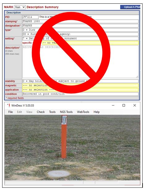
Fig. A.1 For submitting a GNSS project to NGS for publication, a complete set of description files are needed. Mark descriptive summary as shown on the Mark Page is not sufficient.
WinDesc enables the creation, editing, and formatting of geodetic control description information in compliance with the National Geodetic Survey’s Bluebook Annex P. WinDesc uses scripts that query the NGS database, to ensure consistency.
The software is designed for Microsoft Windows Operating Systems, and has been tested on Windows 7, 8 and 10. Note: The spelling check routine will only work if Microsoft Word is loaded on the PC.
WinDesc is available from the NGS website: NGS website. Check the website periodically for new versions of the program, or, within WinDesc, navigate to the WebTools –> Update –> Program menu. Be sure to uninstall the old version before installing the new one. The program will prompt for intermediate updates periodically. Access to the internet is required to download updates.
Photos are critical pieces of corroborating evidence in mark descriptions, and need to be loaded into OP. Users are directed to the NGS Photo Submission Guidelines for more information. We recommend using the photo editing features within WinDesc, and then uploading photos to OP after all observation files have been loaded.
A.2. Creating a New Description File
Select: ‘File>New’ from the menu, as shown in Fig. A.2, or press Ctrl N. Type in the name of the file to be created.

Fig. A.2 Home screen WinDesc version 5.03.03, showing the initiation of a new description file
This will create a new *.des file in the directory that you have selected, as shown in Fig. A.3.
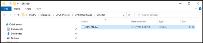
Fig. A.3 Sample description file for a fictitious project “GPS1234”
The name you give the description file should make sense to you, but it does not matter what you name it, as OPUS Projects will rename the file once it is uploaded to the project.
A.3. Editing Project Data
Select ‘Edit>Project Data’ from the main menu (Fig. A.4) to access the project data form, as shown in Fig. A.5.

Fig. A.4 Accessing Project Data in WinDesc
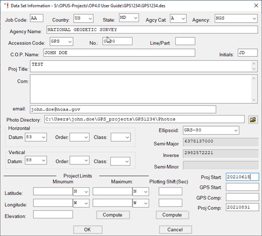
Fig. A.5 Sample WinDesc Project Data screen
Job Code: User-defined as needed, but recommended to always use “AA.”
Country: Select appropriate country for project from the drop-down menu.
State: Select appropriate state for project from the drop-down menu.
Agcy Cat Code: Drop-down menu; select the appropriate category for you/your agency, as shown in Fig. A.6. The category codes help organize and identify the “agency” assigned to the user for the purpose of submitting information and data to the National Geodetic Survey. Note that a private individual, or “none” as codes can be found under “M - Non-Specific Designators.”
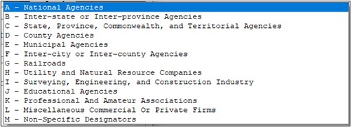
Fig. A.6 NGS Agency categories drop-down menu
Agcy symb: When the Agency Category Code is selected, the corresponding available Agency Codes are available in the drop-down menu. You can type the Agency Code or scroll to the correct code. Once the code field is entered, the Agency Name will fill in automatically.
If a user is not sure whether their agency has a code they can look it up in the Contrib.dat file (found in the PC’s WinDesc folder), or look it up online: (https://geodesy.noaa.gov/cgi-bin/get_contrib.prl).
If a user cannot find the corresponding agency and would like to register the agency, the user can send an email request to ngs.annexc@noaa.gov.
Accession Code: For any GPS project, accession code is “GPS.”
[Accession] No.: This field can be left blank.
Line/Part: This field can also be left blank.
C.O.P. Name: Enter the Chief of Party name.
Initials: Enter the Chief of Party initials.
Proj. Title: Enter the name of the project (it is recommended to use the same name as the one used in OP).
Com.: Comments are optional.
Email: Sharing an email address will allow NGS to contact you if there are any issues or questions about your description files.
Photo Directory: Processing mark descriptions in WinDesc allows the user to correctly format, edit, and label all the required photos for the project. Identifying the directory containing all of the photos simplifies the identification and processing of the photos.
Horizontal/Datum/Order/Class: At the time of this writing, NGS only accepts projects consistent with NAD 83.
Vertical/Datum/Order/Class: This field can be left blank.
Ellipsoid: Leave blank or select GRS-80.
Project Limits: Leave blank.
Proj Start and GPS Start: Enter the date (yyyymmdd) that the project and GPS observations started. GPS Comp and Proj Comp: Enter the date (yyyymmdd) on which the GPS observations were completed and the project was completed.
Click OK to save the project data.
A.4. Editing Descriptive Data
Select Edit –> Descriptive Data from the top menu (Fig. A.7) to open the Descriptive Data window, as shown in Fig. A.8.
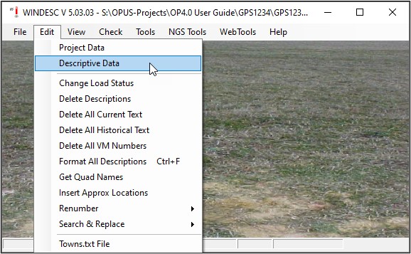
Fig. A.7 Accessing the mark Descriptive Data in WinDesc

Fig. A.8 Sample mark description for a published mark (information downloaded from the NGS IDB)
SSN (Station Serial Number): Each survey mark is assigned a unique station serial number (SSN) in the range 0001 to 9999. Each SSN needs to be unique to each user mark observed in the project. It is recommended to use a sequence of SSNs such as 1001, 1002, 1003, etc, and the order of the marks is irrelevant for OP. Note that the 9000 series is typically used for marks not found or destroyed marks. Using the 9000 series for existing marks recovered in good condition or for marks not yet in the NGS IDB will trigger a warning.
Danger
The SSNs of the WinDesc file must mach the SSNs in OP
DNR: Describe a new mark (D) or Recover and existing mark (R); N is used to signify a mark searched for but not found (see Fig. A.9).
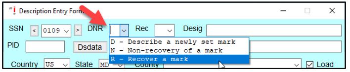
Fig. A.9 Describe, Non-recover, or Recovery a mark options
A.4.1. Recovering an Existing Mark in the NGS IDB
If the mark already exists in the NGS IDB, the user will typically modify (add to) the existing description of a mark in the description file. In rare cases, the user may wish to totally re-describe a mark, if the original description is deemed incorrect or inadequate.
Rec (Recovery): If an existing mark is recovered (R code, above), then the user can select from the following (see Fig. A.10):
F: Fully describe a mark not already present in the NGS database M: Modify (add to) the description of an existing mark in the NGS database T: Totally re-describe a mark in the NGS database
Note: If a mark is not a newly set mark, but does not exist in the NGS database (e.g. an older mark from another agency), it is still a Recovery, and the recovery type will be F - fully describe a mark not in the NGS IDB.

Fig. A.10 Fully describe, Modify, or Totally re-describe a mark options
Desig (Designation): Since the mark already exists in the database, this field can be skipped. Go straight to the PID, below.
PID (Permanent Identifier): This is the unique, six-character code identifying the mark within the NGS IDB. The first two characters are alphabetic, followed by four numeric characters (e.g. “AB1234”).
After the PID is entered on the second row of the description entry window, the user can click on the Dsdata button to retrieve mark descriptive information already loaded in the NGS IDB, as shown in Fig. A.11. The information will be retrieved from the internet, assuming there is an internet connection; if there is no internet, the user will have to have previously downloaded a datasheet file for each mark in the NGS database.

Fig. A.11 Pop-up window prompting user to import mark descriptive data from an existing mark in the NGS IDB (using the mark’s PID)
Once the description file incorporates the relevant metadata from the NGS database, Windesc adds additional information to the right of the SSN drop-down menu (see below): the first column gives the horizontal order assigned to the mark (this is an obsolete code); the middle column gives the vertical order; and the right-most column identifies the source of the height. In the example provided in Fig. A.12, the zeros for horizontal order implies no order is assigned to the marks current position in the NGS IDB. The marks shown with either First Order or Second Order heights are shown to have an adjusted (“A”) height. The one mark with neither First nor Second Order heights is GPS-derived (“G”).
The user should verify that the information loaded onto the description pages is correct (including the “Position” and “Text” buttons, explained below).
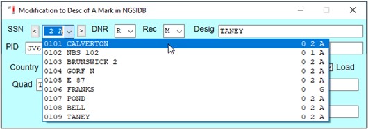
Fig. A.12 Additional mark attributes imported from the NGS IDB
Country/State/County/Quad: These should be correctly imported from the NGS IDB, but it is always prudent to check (Quad refers to the corresponding USGS 7-minute quadrangle map).
Load: The load box should be checked if the marks description/recovery is intended for loading into the NGS IDB.
VM: If the mark is associated with a water level mark, a tidal bench mark, or is a vertical datum point, it will also have a Vertical Mark (VM) number. The number is available from the Tides & Currents bench mark datasheet pages.
GPS: This describes whether the mark is suitable for GPS observations. For marks with observations in OP, this must be “Y” (Yes, mark is suitable for GPS use).
ID: This is a four-character ID assigned to each observed mark in your GNSS project. Although this field in WinDesc is not required, it may be helpful in cross-referencing mark descriptive information with the correct user mark in OP.
Recovery Information: if the mark is an existing mark, the description file needs information on the agency, date, and Chief of Party associated with the recovery, as shown in Fig. A.13. As before, agency information starts with the agency type, followed by the specific agency name code (See Bluebook Annex C for more information). The user may also consult the Agency Table, and email ngs.annexc@noaa.gov if a new agency code is required.
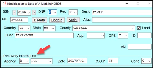
Fig. A.13 Mark recovery information
Surface Marker Information
For a mark already in the NGS IDB, the surface marker information will have been imported from the database, as shown in Fig. A.14. Occasionally, some information may be missing, which the user may be able to provide. It is always recommended to check to make sure all of the information is correct. Any user-changed fields will be reported in the “Discrepancy” analysis (*.dis file; A.5.2) and should be noted in the project report.

Fig. A.14 Surface Marker Information
Cat: This is the category of the mark, whether it be a disk, rod mark, landmark, or other.
Type: This is the specific attribute for the mark category. For survey disks, there are a number of types including generic survey disks, tide station disks, vertical control disks, etc. For rod marks, options include flange-encased rod or simply metal rod.
Mag: If the mark is known to have magnetic properties (it can be located with a metal detector), please indicate it here.
Stability: This is the presumed stability (combined horizontal and vertical) of the survey mark. Is the mark subject to disturbance or movement? Please refer to Table A-1 for an explanation of the stability codes.
Vertical Stability Code |
Definition |
Example |
|---|---|---|
A |
Marks of the most reliable nature which are expected to hold their position/elevation well |
Marks set on outcrops, on foundations of huge structures, or deep rod marks inserted to refusal |
B |
Marks which probably hold their positions/elevations well |
Marks set on foundations of large structures, or deep rod marks |
C |
Marks which may hold their positions/elevations well, but which are commonly subject to surface ground movements |
Marks set in medium structures, including concrete post marks |
D |
Marks of questionable or unknown reliability |
Marks set in light structures (e.g. sidewalks, curbs, etc.) |
If a stability code has already been assigned to the mark in the NGS database, only change the stability code if there is proof positive that the original stability is mis-characterized (please provide evidence, such as a photograph).
Fl/Proj/Rec (Flush/Projecting/Recessed): this refers to where the mark is found relative to the surrounding ground. If the mark is not flush with the ground, please provide a measurement of the distance that it is either projecting (P) or recessed (R). Note that either centimeters, inches, or feet are allowed.
Setting: This refers to the structure to which the survey mark is attached. Review for accuracy. If the current setting is different than what is indicated in the database, there is either an error in the database, or the mark has been reset. In either case, a note in the text would be warranted.
Setting Phrase: This is a concise (one or several-word) description of the specific setting of the mark. Examples might include “bridge,” “abutment,” “pier,” etc. Review as above, and correct if necessary, adding explanatory text.
Logo: This part of the description relates to the agency that set the mark. Typically a survey mark will have the agency logo cast into the disk or mark access cover. Review for accuracy.
Stamp: This refers to the exact stamping seen on the disk or mark access cover. Typically this includes the designation as well as the year the mark was set. Note that the agency logo information is NOT included in the definition of the stamping - only the designation, year, and possibly other text stamped into that particular mark. If there are more than one year stamped on the disk, that is most likely an indication that the original mark has been reset. Review the descriptive information for reference to the mark being a reset.
Underground Marker Setting Information
Traditional horizontal marks set in the 19th and early 20th Centuries involved burying a mark underground to assist with resetting the surface mark if it got destroyed or damaged. Existing data on the original underground mark description can be found or modified here, shown in Fig. A.15. Unless the surface mark is damaged or destroyed, it is not recommended to attempt to recover the underground mark. Therefore, these attributes are merely checked but generally not modified.

Fig. A.15 Underground marker information
Type: This is similar to the mark type seen earlier, and actually has more entries for historical reasons.
Mag: If the mark is known to have magnetic properties (it can be located with a metal detector), this should be indicated here.
Stability: This is assumed stability (combined horizontal and vertical) of the underground survey mark.
Setting: This refers to the structure to which the underground survey mark is attached.
Date: This should be the same as the setting date, if known.
Position: By clicking on the Position button on the main description data page, as shown in Fig. A.16, a pop-up window will appear, which will display positional information (Fig. A.17). For marks already in the NGS database, the position information will be displayed. If you are fully describing a mark, this is where you can put in preliminary coordinates from an OPUS solution.

Fig. A.16 Location of the “Position” button on the Description Entry Form
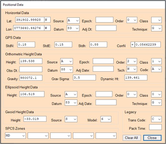
Fig. A.17 Mark Position data page
An explanation of the data fields is provided below. Review the information presented for completeness.
Lat: Input the latitude for the mark, in the DDMMSS.sssss format.
Lon: Input the longitude for the mark, in the DDMMSS.sssss format.
Source: The source is defined from the NGS database. If the source is “s” (Scaled from a map), the user may want to update the coordinates with those obtained from one of the single OPUS solutions obtained after an observation file is loaded into the project. In this case, the source would be “O” (Other).
Datum: Select “83” from the list.
Epoch: Do not define or change.
Adj. Dt.: Do not define or change.
Order: A single OPUS solution is considered Fourth Order.
Class: Not required (leave blank).
Technique: Coordinates derived from a single OPUS solution are considered “Hand Held 1” (differential GPS), which means that the horizontal coordinates will be truncated to two decimal places.
Note that these fields (Source, Order, Class, Technique) relate to the implied precision and accuracy of the horizontal coordinates, which dictates under which conditions a horizontal position in the NGS database can be superseded.
If the precision and accuracy of the horizontal position of a mark is poor in the IDB (e.g. “scaled”), it is recommended to insert the higher precision Lat/Lon’s from an OPUS solution for the corresponding mark.
GPS Data/Orthometric Height Data/Ellipsoid Height Data/Geoid Height Data/SPCS Zones/Legacy: Not needed in OP - leave as-is or blank.
Tip
OP uses positions in the WinDesc file to match mark descriptions with User Marks in the project. For that reason, make sure the positions shown in the Position window are accurate.
Close (Positional Data Window): Click on this button to bring you back to the Description Entry Form page.
Text: If the mark is recovered as described and in good condition, there is no need to add any text. However, if there is any important new information to share about a mark’s condition or location, then it is important to add a description of these changes in the “text” portion of the mark recovery (Figure A-18). Examples would include the absence of one or more reference objects, any changes to the mark’s projection status, and changes in the area surrounding the mark, which may affect the mark’s stability or ability to obtain good GNSS signals.
By clicking on the “Text” button on the main Description Entry Form, as shown in Fig. A.18, a pop-up window will appear in which both historical descriptive text (if available) will appear, as well as a new empty screen for new descriptive text (opened by default), an example is shown in Fig. A.19.
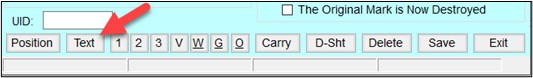
Fig. A.18 Click on the [Save} button to save all mark descriptive information

Fig. A.19 New descriptive text associated with a mark delivery
Note that the text is entered automatically in ALL CAPS. After entering any new text, click on the Format button, which should help format the text appropriately for the datasheet.
For any new text to be loaded successfully, the spell checker will have to be run. Access the spell-checking utility by clicking on the Spelling button. This will open the Spell Check window. Click on the Start button to begin spell checking, as shown in Fig. A.20.

Fig. A.20 The WinDesc Spell Check utility
If any misspelled words are found, or there are words not found in the Spell Check library, the user will be prompted to change, add, or ignore the word, an example is provided in Fig. A.21.
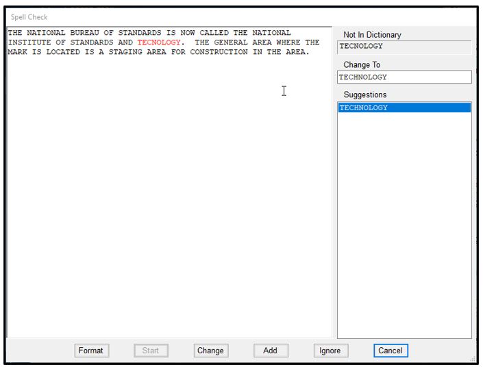
Fig. A.21 Example of a misspelled word identified by the WinDesc Spell Check
Once the entire body of the new text is checked, a pop-up window will alert the user that the checking is complete. The Spell Check utility will unload, and the user can then close the window, as shown in Fig. A.22.
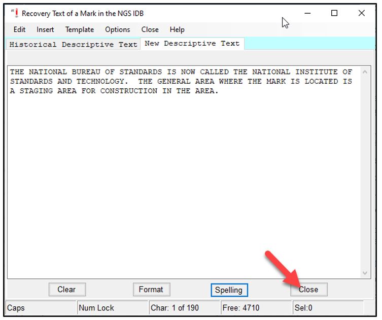
Fig. A.22 Closing the WinDesc Spell Check
Since changes have been made to the mark’s description, you will need to save your changes before proceeding to the next mark, as seen in Fig. A.23.
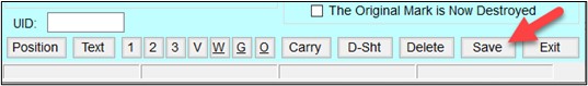
Fig. A.23 Save any changes to the mark description
A.4.2. Describing a New Mark
A new mark is not necessarily a mark that has recently been set. By “new,” we mean that it has not yet been described in the NGS IDB. Whereas recovering a mark entails mostly reviewing existing information, describing a new mark means adding all new information. There are some slight changes to the main description entry form described below in Fig. A.24.
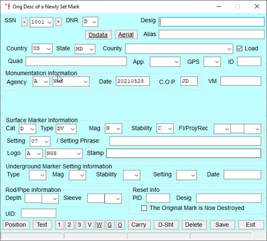
Fig. A.24 Original description of a newly set mark in WinDesc
Note that there is no qualifier for the kind of recovery, and the PID field has disappeared.
Desig: This is typically a number, an alphanumeric symbol, or a concise, intelligible name which is usually stamped on the disk or access cover of the mark.. Guidelines recommend that the designation be unique to the survey mark at least within the same county, if not the same state, to avoid the probability of mis-identification. Please see Annex D of the Bluebook for additional guidance on designations, especially when dealing with legacy marks. The designation must not exceed 30 alphanumeric characters, including all embedded blanks. When necessary, abbreviate the designation to conform to the 30-character rule.
Alias: This is an optional field to enable the user to add a second name associated with the mark.
Country/State/County/Quad: Enter these attributes. Quad refers to the corresponding USGS 7-minute quadrangle map, and will be automatically entered by WinDesc once the Position information is entered (see below).
Load: The load box should be checked if the mark’s description/recovery is intended for loading into the NGS IDB.
App (Application): Identify any special application assigned to the mark from the pull-down menu, as shown in Fig. A.25. This is an optional field that only needs to be specified if there is a special application required. Otherwise leave blank.
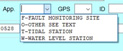
Fig. A.25 Special application options for a new survey mark
GPS: This describes whether the mark is suitable for GNSS observations. For marks with observations in OP, this must be “Y” (Yes, mark is suitable for GNSS use).
ID: This is a four-character ID assigned to each observed mark in your GPS project. Although this field in WinDesc is not required, it may be helpful in cross-referencing mark descriptive information with the correct user mark in OP.
VM: If the mark is associated with a water level mark, a tidal bench mark, or is a vertical datum point, it will also have a Vertical Mark (VM) number. The number is available from the Tides & Currents bench mark datasheet pages.
Monumentation Information: The description file requires information specific to the installation of the mark, as shown in Fig. A.26, including the setting agency information, the date the mark was installed, the Chief of Party (“C.O.P.”). As before, agency information starts with the agency type, followed by the specific agency name code (See Bluebook Annex C for more information). The user may also consult the Agency Table, and email ngs.annexc@noaa.gov if a new agency code is required.
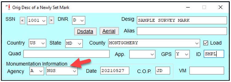
Fig. A.26 Monumentation information for a newly described mark
Surface Marker Information
Cat: This is the category of the mark, whether it be a disk, rod mark, landmark, or other.
Type: This is the specific attribute for the mark category. For survey disks, there are a number of types including generic survey disks, tide station disks, vertical control disks, etc. For rod marks, options include flange-encased rod or simply metal rod.
Mag: If the mark is known to have magnetic properties (it can be located with a metal detector), please indicate it here.
Stability: This is assumed (combined horizontal and vertical) stability of the survey mark. Is the mark subject to disturbance or movement? See table A-1.
Fl/Proj/Rec (Flush/Projecting/Recessed): This refers to where the mark is found relative to the surrounding ground. If the mark is not flush with the ground, please provide a measurement of the distance that it is either projecting (P) or recessed (R). Note that either centimeters, inches, or feet are allowed.
Setting: This refers to the structure to which the survey mark is attached. Please select the appropriate setting code from the available options. If selecting “00” for “Other,” it is recommended to explain the setting in the text portion of the mark description (see below).
Setting Phrase: This is a concise (one or several-word) description of the specific setting of the mark. Examples might include “bridge,” “abutment,” “pier,” etc. Note that the setting phrase is not a repetition of the words used to describe the setting code. By selecting the setting code, the user has already identified the language associated with the code. The Setting Phrase provides the opportunity to add additional explanatory text.
Logo: This part of the description relates to the agency that set the mark. Typically a survey mark will have the agency logo cast into the disk or mark access cover. As before, select the agency type, and agency code (See Bluebook Annex C for more information). The user may also consult the Agency Table, and email ngs.annexc@noaa.gov if a new agency code is required.
Stamp: This refers to the exact stamping seen on the disk or mark access cover. Typically this includes the designation as well as the year the mark was set. Note that the agency logo information is NOT included in the definition of the stamping - only the designation, year, and possibly other text stamped into that particular mark.
Underground Marker Setting Information: Newly set marks are surface marks. If the station has an underground mark, the Type, Mag, Stability, and Setting fields should be entered. They are similar to those seen in the Surface Marker Information. The Type has more options, however, due to historical reasons.
Rod/Pipe Information: If the surface marker is attached to a pipe or rod, the depth needs to be entered in the description, as well as whether or not the rod also has a sleeve (to isolate it from potential movement of the soil surrounding the rod), an example of the required information is provided in Fig. A.27.
Reset Info: If the mark is a reset of an original mark in the NGS IDB, the user can refer to the parent mark here, noting both its PID and designation. Typically, if the new mark is a reset, the original mark is destroyed. If this is known to be the case, the corresponding box can be checked.

Fig. A.27 Rod/Pipe and Reset information
Position: By clicking on the Position button on the main description data page, as shown in Fig. A.28, a pop-up window will appear, which allows positional information to be entered (see Fig. A.29). Enter the best coordinates you have for the mark. The position entered here will be used to correctly match the mark’s description to the corresponding mark in OPUS.

Fig. A.28 Location of the “Position” button on the Description Entry Form

Fig. A.29 Mark Position data page
For a mark that does not have a PID (it does not exist in the NGS IDB), it is recommended to enter the position from one of the single OPUS solutions generated when the data file was uploaded into the project.
Lat: Input the latitude for the mark, in the DDMMSS.sssss format (enter only as many significant digits as your data source gives you).
Lon: Input the longitude for the mark, in the DDMMSS.sssss format (enter only as many significant digits as your data source gives you).
Source: If entering the position from an OPUS solution, this would be “O” for “Other”.
Datum: Select “83” from the list.
Epoch: Not required (leave blank).
Adj. Dt.: Not required (leave blank).
Order: A single OPUS solution (or hand-held coordinate) is considered Fourth Order.
Class: Not required (leave blank).
Technique: Coordinates derived from a single OPUS solution are considered “Hand Held 1” (differential GPS), which means that the horizontal coordinates will be truncated to two decimal places.
GPS Data/Orthometric Height Data/Ellipsoid Height Data/Geoid Height Data/SPCS Zones/Legacy: This information is not needed to generate a complete description file, so it can be left as-is.
Danger
Make sure any coordinates associated with new marks are accurate in the Position window, otherwise, this will cause problems in OP
Close (Position Window): Click on this button to bring you back to the Description Entry Form page.
New Descriptive Text: A new mark will need a complete descriptive text indicating where the mark is located and how to reach it. A separate text window is accessed by clicking on the Text button at the bottom of the Description Entry Form, as shown in Fig. A.30.

Fig. A.30 Click on the [Text} button to add descriptive text to a mark

Fig. A.31 Example of new descriptive text in the recommended three-paragraph form
A complete, new descriptive text is typically given in a three-paragraph form shown above in Fig. A.31. The first paragraph identifies where the mark site is located within a general area. Distances to the nearest town center or references to major landmarks are given. The second paragraph describes how to reach the mark site from the nearest road intersections. The third paragraph explains how to find the mark once the site is reached. Measured distances (to the nearest decimal meter) are given to five reference objects, to ensure that the mark can be recovered even if several reference objects disappear over time.
Note that the text is entered automatically in ALL CAPS. After entering new text, click on the Format button, as shown in Fig. A.32, which should help format the text appropriately for the datasheet.
![The [Format] button on the mark descriptive text page](_images/FigureA-32.jpg)
Fig. A.32 The [Format] button on the mark descriptive text page
Spell checker needs to be run on all new text. Access the spell-checking utility by clicking on the Spelling button. This will open the Spell Check window. Click on the Start button to begin spell checking, as shown in Fig. A.33.
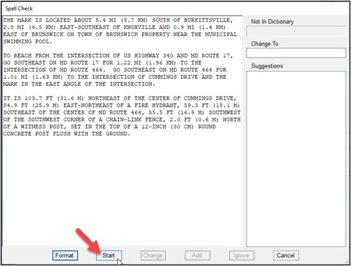
Fig. A.33 The WinDesc Spell Check utility
If any misspelled words are found, or there are words not found in the Spell Check library, the user will be prompted to change, add, or ignore the word. An example is shown in Fig. A.34 below.

Fig. A.34 Example of a misspelled word identified by the WinDesc Spell Check
Once the entire body of the new text is checked, a pop-up window will alert the user that the checking is complete. The Spell Check utility will unload, and the user can then close the window, as shown in Fig. A.35.
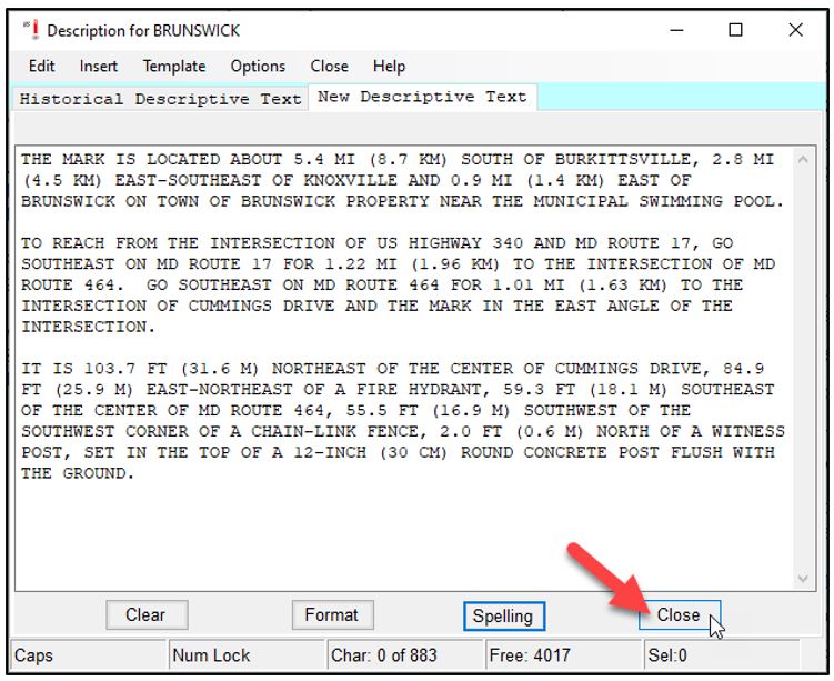
Fig. A.35 Closing the WinDesc Spell Check
Since changes have been made to the mark’s description, you will need to save your changes before proceeding to the next mark, as shown in Fig. A.36.

Fig. A.36 Save any changes made to the mark description
You do not need to include descriptions for the CORS stations in your project. However, if you are including Non-NCN CORS data in your project that is not in the NGS IDB, a “new” description is required. A sample mark description for a Non-NCN CORS station is provided below in Fig. A.37 and Fig. A.38.
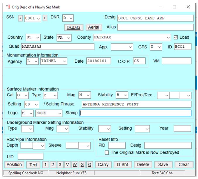
Fig. A.37 Sample mark description for Non-NCN CORS station
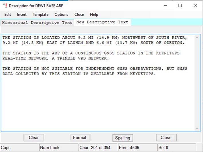
Fig. A.38 Example of new descriptive text in the recommended three-paragraph form for a Non-NCN CORS station
Tip
CORS stations in the NGS IDB do not need to be included in the description files. However, Non-NCN CORS stations will need to be included as a “new” mark.
A.4.3. Photo Editing
Photos are an important part of the mark description, as they provide evidence of the mark itself, as well as its condition. Regardless of whether a mark is newly described, or already exists in the NGS IDB, a set of three photographs are required for submitting a GNSS project to NGS. WinDesc provides easy access to a photo editor which can simplify the process of implementing the NGS Photo Submission Guidelines. If the photo directory has been properly identified under Project Data (Figure A-5), clicking on the <1> <2> and <3> buttons will enable you to select the correct close-up of the mark (Photo #1), eye-level photo of the mark (Photo #2), or horizon view (Photo #3), respectively (see Fig. A.39). If you are the owner or manager of a Non-NCN CORS station that is included in your project, photos of your station are recommended (only if they can be safely obtained without interfering with the equipment). For Non-NCN CORS stations the three alternative photos are the antenna serial number (Photo #1), receiver serial number (Photo #2), and a station setup (Photo #3). See Fig. 5.4 for examples.

Fig. A.39 Three buttons at the bottom of the Description Entry Form enable you to properly edit the three required photos for each mark in the project
The WinDesc photo editing features include resizing, cropping the image, rotating, placing a standard (or custom) label on the image, and more. An example that illustrates adding a label to an image is shown in Fig. A.40.

Fig. A.40 Example showing the creation of a standard label for a survey mark close-up photograph
With typical high resolution digital cameras, mark photographs are often larger than needed and may also be too large to display properly on a computer screen. For that reason, NGS recommends a square 400 x 400 pixel size closeup photo (#1) and a 1024 x 768 pixel photo size for photo #2 and #3. WinDesc offers an easy way to resize a photo, as shown in Fig. A.41.
Once the photo has been correctly edited, the user can save and exit the photo editing window to return to the main descriptive entry window. This step is illustrated in Fig. A.42.
Once photos have been formatted, edited, and named correctly using WinDesc, they can be loaded into OP. There is no bulk-upload method available at this time, so all photos will need to be uploaded individually. We recommend that photographs be uploaded within OP’s User Mark pages after all RINEX observations have been uploaded (see Section 7.3.7 of the OP User Guide).

Fig. A.41 Using WinDesc to resize a survey mark photo
Fig. A.42 Saving and exiting the WinDesc photo editing window
Tip
It is recommended to use WinDesc to properly format photos prior to loading into your project
A.4.4. Additional features
WinDesc provides additional features, accessible from the buttons along the bottom of the Description Entry Form. Most of these are typically not required in OP, but are explained below for thoroughness:
V: Use this button to ensure the correct naming of any associated visibility diagram for the mark. Although OP does not support the inclusion of visibility diagrams within the project, certain surveys may require visibility diagrams be submitted (separately) for the project to be accepted by NGS. Please refer to your project instructions regarding whether or not to submit visibility diagrams.
W: Use this button to view the photos previously loaded into the NGS database for this mark. This can help verify that the correct mark was included in the project.
G: Use this button to check the geocaching website for additional photographic evidence of the mark.
O: Use this button to view photos from the OPUS Share database, if available.
Carry: Enables you to carry descriptive information to another mark in your project (may be useful if you are building a large description file of new marks which are similar in numerous mark attributes).
D-SHT: Creates a preliminary datasheet for the mark given the information you have provided.
Delete: Deletes this particular description (for the SSN shown at the top of the form) from the description file.
When you have completed your mark description, click on <Save> before proceeding to the next mark in your project, as shown in Fig. A.43.
![The [Save] button at the bottom of the Description Entry Form](_images/FigureA-43.jpg)
Fig. A.43 The [Save] button at the bottom of the Description Entry Form
A.5. Checking the Description File
A.5.1. Neighbor for all Marks
This check is accessed from the Web Tools tab (see Fig. A.44). Running “neighbors” identifies and lists all marks currently in the NGS database that are within a specified distance from each mark in the description file (based on the position data in each marks description).
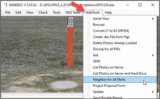
Fig. A.44 Accessing the “Neighbor for all Marks” check in WinDesc
Accept the defaults (400 m radius, and do not include temporary bench marks, or TBMs), as shown in Fig. A.45 and Fig. A.46.
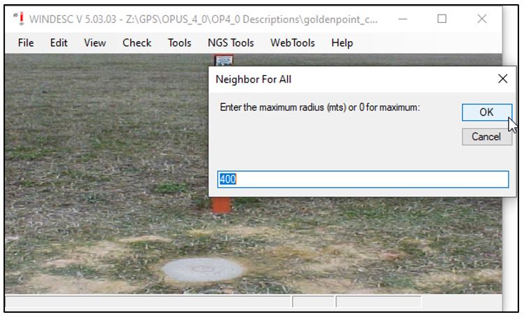
Fig. A.45 Default maximum radius for checking neighboring marks in WinDesc
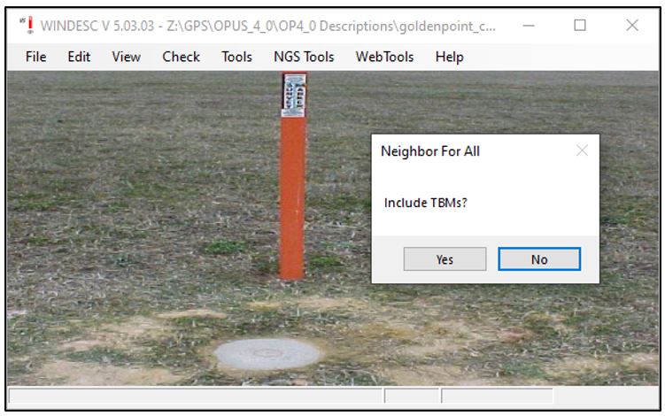
Fig. A.46 Option to include TBMs (Temporary Bench Marks) in the WinDesc neighor analysis
The output is a text file (*.nbr, shown in Fig. A.47) that lists all marks within the specified distance, sorted from nearest to farthest. If the mark already exists in the NGS database, the mark should appear at the top of the list. Note that there can be a slight discrepancy in the distance if an updated position has been entered.

Fig. A.47 The result of a neighbor analysis in WinDesc
Running neighbors is required to make sure that the user has correctly identified the mark. This is especially important if the mark is part of a set of classical horizontal marks, which may include the horizontal mark itself, as well as reference marks and azimuth marks: all marks in the set may share much of the same designation, which can easily cause confusion and mis-identification (e.g. confusing a reference mark for the horizontal mark itself). Review the information to make sure the correct mark has been included in the description file. Also, many marks already exist in the NGS IDB but do not have publishable datasheets. Neighbor will list all marks in the area, regardless of whether or not their datasheets are publishable. This can be important in determining whether a “new” mark actually already has a PID. The output table is sorted by distance from the input mark’s position to the position of nearby marks in the NGS database. The *.nbr file is saved to the same directory as the description file itself.
A.5.2. Discrep for all PIDs
This utility identifies and flags all discrepancies between information in the NGS database and the description file. Fig. A.48 illustrates how to access this feature. This ensures that the user is made aware of how the new description file may differ from published datasheets. Common causes for discrepancies include newly identifying the mark as good for satellite observations, or a better source for the horizontal data.
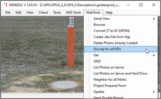
Fig. A.48 Accessing the Discrepancy analysis in WinDesc
The output of Discrep is a text file (*.dis, shown in Fig. A.49) with only those attributes listed that are at variance with the NGS database. The left column is for the new description, the right column is for information currently in the database. In the example, no discrepancies are found for CALVERTON, NBS 102, or BRUNSWICK 2. However, GORF N shows a discrepancy in the designation. Also note that for E 87, a more recent recovery was made (2018 vs. 2017), and indicating a different distance of the mark above (P) or below (R) ground (20 vs. 15). All discrepancies must be considered. Re-run Discrep after all changes, if any, are made to the description file. Any remaining discrepancies should be explained in the final project report.
Remember, a discrepancy is not necessarily an error, but a warning. Your report should indicate that you have run, checked, and verified all discrepancies in the (*.dis) file.
Caution
The updated position will show up as a discrepancy.
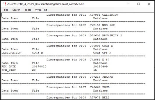
Fig. A.49 Sample Discrepancy report showing differences between the description file and information in the NGS IDB
The *.dis file is saved to the same directory as the description file itself.
Caution
Discrepancies do not necessarily mean errors. Verify to make sure any discrepancy is indeed correct.
A.5.3. Exporting the Description File and Error Checking
The final steps in preparing the description file involves converting it into a format required for loading into the NGS database, and running a final error check. The export functionality will convert the native WinDesc (*.des) file format into a somewhat reduced file format readable in Linux, so the file can be loaded into the NGS IDB, as shown in Fig. A.50.

Fig. A.50 Exporting the description file
In executing the export script, WinDesc will prompt the user to run a final error check (see Fig. A.51).
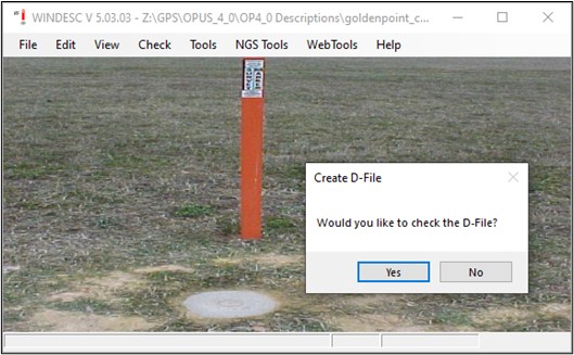
Fig. A.51 WinDesc prompts the user to run a final error check after exporting the description file
In the error checking process a *.err file will be created, which lists all the errors found. Typical errors include required stamping information, special characters or other errors in the designation, or additional information required for certain mark setting types. The error checking can detect logical or inconsistency errors in the mark description fields, but it cannot always pinpoint exactly what is wrong. There may therefore be several warnings or errors flagged for a particular mark (identified by its SSN). For submitting the description file to NGS (as part of the OPUS Projects GNSS project), all errors must be resolved (it is permissible to have some warnings, as shown in Fig. A.52).
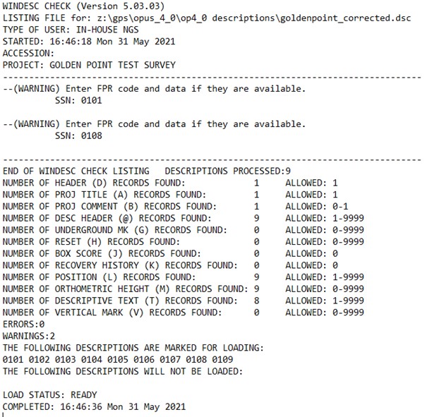
Fig. A.52 Sample error (*.err) file
Warnings often request additional information pertaining to whether the mark is flush with the ground, projecting, or recessed (FPR in the example above). Other warnings might pertain to mark setting codes expecting additional information. Review the warnings to make sure you have provided correct, relevant information.
Caution
Any and all errors MUST be resolved prior to loading the description file into OP
A.6. Organizing Files to Upload to OP
As a result of creating, building, checking, and exporting a full description file for your project, you will have five separate files ready to upload to OP:
The description file in its native WinDesc format (e.g. GPS9056.des)
The description file in a Linux-uploadable, condensed format (e.g. gps9056.dsc)
A listing of neighbors (e.g. GPS056.nbr)
A listing of discrepancies with the NGS database (e.g. GPS9056.dis)
The final error checking file (e.g. GPS9056.err)
All five (5) files are required before the Submit For Publication button becomes active.
A.7. Checking Coordinates Prior to Network Adjustments in OP
The Index File is a convenient way to check that the geometric coordinates, reference frame, heights, and vertical datum are all correct. Fig. A.53 shows how to create the index file and a sample file is shown in Fig. A.54.
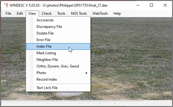
Fig. A.53 How to create the WinDesc index file
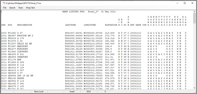
Fig. A.54 An example of a WinDesc index file showing the SSNs, PIDs, Designations,, coordinates, elevations, and other descriptive information
This can be very helpful for larger projects, so one does not have to manually review each individual user mark page. The index file can be saved and imported into a spreadsheet or other software to assist in validation/verification.
WinDesc also provides a utility to display the network accuracies of the coordinates if they were based on GNSS. These values are found on the NGS datasheets under “Network accuracy estimates.” WinDesc provides an easy way to view them all in tabular form. First, the user must download the data from the NGS IDB using Web Tools –> Get –> Pos & Acc for GPS PIDs, as shown in Fig. A.55.

Fig. A.55 How to download network accuracies for all marks whose coordinates in the NGS IDB were based on GNSS observations
Next, the user can view the Accuracies file from the View menu, as shown in Fig. A.56 and Fig. A.57.
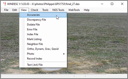
Fig. A.56 How to view position accuracies on marks in WinDesc
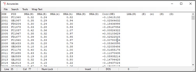
Fig. A.57 Network accuracies and correlations for marks in the description file whose positions in the NGS IDB were determined from GNSS observations
Accuracies can be compared to those given in OP (a priori coordinates and sigmas). The WinDesc Accuracies file can also be saved and imported into a spreadsheet program if desired.